
A6500-RC-SYSTEM-RELAY-CARD-EN-9881078
Application
The A6500-RC Relay Card is a component of the AMS 6500 ATG machine protection system. It is a freely programmable microprocessor-controlled module that can be used to do logical combination of binary signals within a AMS 6500 ATG system. When connected to an A6500-xR System Rack, the measurement cards provide and connect their logical outputs (COK, Alert, and Danger) automatically to the A6500-RC inputs through the backplane of the System Rack.
The A6500-RC captures the signals to logically combine them and provide the results through relay outputs. The A6500-RC is intended to be used in an A6500-xR System Rack (A6500-SR, A6500-RR, or A6500-FR) which is equipped with a separate slot for the A6500- RC.
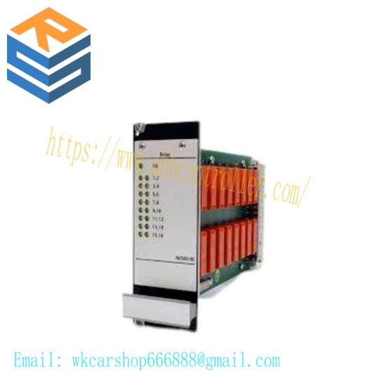
The A6500-RC Relay Card is equipped with 66 digital, galvanically separated input channels (24 V logic), 16 output relays, one green system status LED and 16 yellow relay status LEDs on the monitor front to indicate the output relay statuses. All 66 input channels can be used separately and can thus be combined with each other individually. The 16 output relay channels are designed as single-pole switchover contacts (SPDT).
Connection of external digital signals is possible if using an A6500-RR system rack or an A6500-FR system rack. The A6500-RC card is not mandatory for the operation of an AMS 6500 ATG.
In conjunction with the A6500-CC Com Card status data of the A6500-RC can be provided through Modbus RTU, Modbus TCP/IP and OPC UA. As the Relay Card is designed for use with A6500-xR System Racks , generally a Com Card is required for configuration purposes.
Design
The A6500-RC Relay Card is designed as a double-standard Euro card (100 mm x 160 mm). The mechanical dimensions of the card match the dimensions of corresponding A6500-xR System Racks exactly. The front plate dimension of the A6500-RC is 3RU height and 10HP width. As the A6500-RC is manufactured in sandwich board design, the main board is equipped with a 96-pole terminal connector and the relay board is equipped with a 48- pole terminal connector (IEC 60603-2, F 48 M) to connect the respective backplane slot. Figure 3-1 shows the side view of the Relay Card.
Installation
For installation and mounting of the A6500-RC into an A6500-xR System Rack the relay output terminals and wiring are described in the operation manual of the A6500-xR System Racks. The Relay Card can be only installed in the double slot 12 (12.1 and 12.2) of the A6500-SR System Rack or in the double slots 10 (10.1 and 10.2) and 11 (11.1 and 11.2) of the A6500-RR System Rack.
General configuration procedure
The configuration can be performed offline, that means without connection to the card or online with a connection to the card. In any case, the configuration has to be loaded into the card. The A6500-CC Com Card is required for the configuration procedure. See Com Card operating manual for details.
Requirements:
A6500-CC Com Card (only online configuration)
A6500-RC Relay Card installed in an A6500-xR System Rack (only online configuration)
Power supply (only online configuration)
USB cable with Type-A and Type-B plug or Ethernet cable (only online configuration)
AMS Machine Studio (configuration software)
PC or laptop with Microsoft Windows 10
These buttons are available when a Module page is selected from the list of configuration pages. Use the Editor and Online buttons to toggle between the editor view and the online view. The button of the selected view is highlighted.
Editor In the editor view, configure logics as described in Module 1 to Module 32
Online In the online view, check the configured logics already stored in the A6500-RC. The online view requires an online connection to the A6500-RC card and no changes in any Module. To ensure that the shown configuration is the configuration stored in the A6500-RC card click Reload (see Reload).
Note
To check a changed Module, send the configuration with the changes to the A6500-RC before.
It is not possible to make any changes to the configuration in the online view except to Basic. Switch back to the editor view to change logics.
Simulate input signals to see if the created logic reacts as expected. How to simulate input signals is described in Functional check.
Elements are colored based on their logic state:
Elements that are logic 1 are colored red
Elements that are logic 0 are colored blue.
Current timer values are colored green.
The logic state is also shown with 1 or 0 at the input and output of each element. See Figure 6-18.
The online view requires a stable connection between AMS Machine Studio and the A6500-RC card, otherwise the logic values cannot be displayed. A disturbed connection is indicated with the note shown in Figure 6-19.
Related product recommendations:
ALSTOM AB121
3BHE014023R0101 UFC789AE101
PPD513AOC-100440 3BHE039724R0C3D
6DS1916-8AA
KJ3102X1-BE1
IS200EMIOH1AFB
VE4017P0
51405098-100
TC-201-01-4M5
KJ3222X1-BA1
5301-MBP-DFCM
6ES7 953-8LG30
3BHT300054R3/A XI-11
TTM211 IP166 L54E60000311
IS200TVBAH2A
IC3600VMPA1E
Bently Nevada 3500/72M-03-01
1KGT030400R0001
Bently Nevada 74712-06-05-03-00
more……
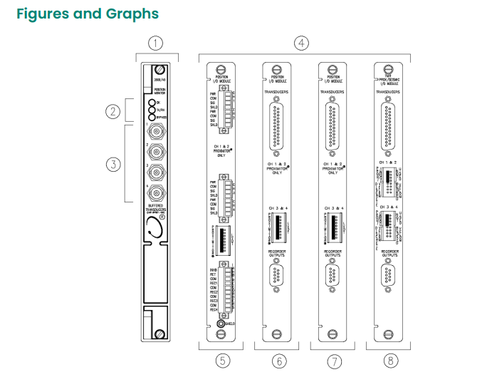 1. Front View of