PLC Dragon Automation
All Categories
Call us 24/7+86 18030295882

Install the AADvance System-T9110

The system installation defines the steps that will verify that the system is correctly installed and ready for the on-site factory tests before the system is brought on-line. This chapter describes how to install the AADvance® system hardware into the chosen enclosure.

Unpacking and Preassembly Checks

The components are packed to make sure they arrive undamaged and ready for assembly. Nevertheless, you should inspect all modules before beginning the assembly work.ABC Electronics T9100 Processor Module Standard Series

On receipt, carefully inspect all the shipping cartons for damage.

• If any cartons are damaged, note the damage on the carrier’s shipping document before signing it. Save any damaged cartons for inspection by the carrier.

• If any part of the delivered components has been damaged during shipping, notify the carrier and Rockwell Automation immediately.

Damaged goods must be returned Rockwell Automation for repair or replacement (see Warranty and Returns instructions with delivery documentation).

Install Base Units and Termination Assemblies: Enclosure DIN Rail Assembly Method

The following illustration shows how to it the backplanes on to Din rails and use the retaining clips and leverto hold them in position.

For a system build that uses DIN rails do the following:

1. Install the DIN rails.

• The AADvance controller will be mounted onto one or more pairs of parallel DIN rails. For each pair ofrails, mount the lowerrail with its center line 101.0mm below the center line of the upper rail. M5 thread rolling screws are suitable.

2. Mount the T9100 processor base unit

• Place the T9100 processor base unit onto the DIN rails and position it towards the left, leaving space for the T9300 I/O base units to the right.

• Secure the processor base unit onto the DIN rails by sliding the retaining lever(below the base unit) to the left.

3. Mount each T9300 I/O base unit

• Place a T9300 I/O base unit onto the DIN rails to the right of the T9100 processor base unit.

• Slide the I/O base unit to the left until the joining connectors are fully mated.

• Insert the retaining clips at the top and bottom of the base units.

• Secure the I/O base unit onto the DIN rails by sliding the retaining lever (below the base unit) to the left. Then insert the backplane clips into the top and the bottom slots.

4. Mount end stops onto DIN rails.

Install two end stops onto the upper DIN rail, one at each end of the assembly.

Fitting Termination Assemblies

• Insert the retaining clip on the back of the termination assembly into the slot on the I/O base unit. Press the termination assembly onto the baseunit and then slide the assembly upwards as far as it will go.

• Make sure the retaining tab clips over the printed circuit board to secure the termination assembly in position.

2. Check coding pegs.

• Observe the legend on the T9100 processor base unit (and repeated on some termination assemblies) which defines the six possible positions for a coding peg. The positions are numbered from 1 to 6.

Connect the AC Safety Ground Connection

The T9100 processor base unit has a ground stud which must be connected to the AC safety ground. Connect the ground stud to the AC safety ground busbar of the system or panel.

• Conductor wire must be a minimum of 12 AWG (3.31 mm2) with a temperature rating of 85 ºC.

• Use a M6 lug on the end of the ground wire.

• Place the lug below the second nut on the ground stud, between two washers, and use two 10mm wrenches to tighten the nuts to a torque of 1.2 Nm to 2 Nm (0.88 lb./ft. to 1.48 lb./ft.).

Refer to the photograph of the 24 Vdc Power Connectors the earth stud is shown between the two powerleads.
Related product recommendations:
Fanuc A06B-6105-H001RJ3
ABB 3BSE011181R1 PM511V16 
DAIHEN UM356B L21700M03
Vacon PC00459G – CM210901
NI PCI-6111
Bently Nevada 330103-00-03-10-02-05
ABB 1SAP250300R0001
Reliance Drive Module 0-57652-E
A-B 6176M-19VN
Yokogawa 5458-050
Schneider Electric 990XCP98000
Honeywell 51402497-200
Allen Bradley 440T-MKEXE16
A-B 80026-381-08 
Honeywell 51304163-300MODEM
ABB 3BSC610067R1
Rexroth PPC-R02.2N-N-NN-P2-NN-FW
Allen Bradley 1746-OV32
ABB 3HNA015717-001
More…

Tricon™ v9–v11 Systems – Planning and Installation Guide-3009

Controller Features

The Tricon controller is a state-of-the-art programmable logic and process controller that provides a high level of system fault tolerance. To ensure the highest possible system integrity at all times, the Tricon controller includes these features:

Provides Triple Modular Redundant (TMR) architecture whereby each of three identical system channels independently executes the control program, and specialized hardware/software mechanisms “vote” all inputs and outputs.Triconex Tricon 3721 Analog Input Module, Industrial Automation Control

Withstands harsh industrial environments.

Enables field installation and repair to be done at the module level while the controller remains online. Replacing an I/O module does not disturb field wiring.

Supports up to 118 I/O modules (analog and digital) and optional communication modules that interface with Modbus masters and slaves, Foxboro® and Honeywell™ Distributed Control Systems (DCS), other Triconex controllers in Peer-to-Peer networks, and external host applications on Ethernet networks.

Provides integral support for remote I/O modules located as far away as 7.5 miles (12 kilometers) from the Main Chassis, using SRXM modules.

Executes control programs developed and debugged with TriStation™ 1131 Developer’s Workbench Software or TriStation MSW software.

Provides intelligence in the input and output modules to reduce the workload of the Main Processors. Each I/O module has three microprocessors. Input module microprocessors filter and debounce the inputs and diagnose hardware faults on the module. Output module microprocessors supply information for the voting of output data, check loopback data from the output terminal for final validation of the output state, and diagnose field-wiring problems.

Provides integral online diagnostics with adaptive-repair capabilities.

Allows normal maintenance while the Tricon controller is operating, without disturbing the controlled process.

Supports transition to a hot-spare I/O module for critical applications where prompt service may not be possible.

Fault Tolerance

Fault tolerance, the most important capability of the Tricon controller, is the ability to detect transient and steady-state error conditions and to take appropriate corrective action online. With fault tolerance, there is an increase in safety and an increase in the availability of the controller and the process being controlled.

The Tricon controller provides fault tolerance through Triple Modular Redundant (TMR) architecture. The controller consists of three identical system channels, except for the Power Modules which are dual-redundant. Each channel independently executes the control program (also referred to as the TriStation application) in parallel with the other two channels. Hardware voting mechanisms qualify and verify all digital inputs and outputs from the field; analog inputs are subject to a mid-value selection process.

Because each channel is isolated from the others, no single-point failure in any channel can pass to another. If a hardware failure occurs in one channel, the faulty channel is overridden by the other channels. Repairs consist of removing and replacing the failed module in the faulty channel while the Tricon controller is online and without process interruption. The controller then reconfigures itself to full TMR operation.

Extensive diagnostics on each channel, module, and functional circuit immediately detect and report operational faults by means of indicators or alarms. The diagnostics also store information about faults in system variables. If faults are detected, the operator can use the diagnostic information to modify control actions or direct maintenance procedures.

Because the triplicated system operates as one control system, the Tricon controller can be programmed with one control program that terminates sensors and actuators at a single wiring terminal.

System Configuration

Physically, a basic Tricon controller consists of Main Processors and I/O modules, communication modules, the chassis enclosing the modules, field wiring connections, and a TriStation PC. This section briefly describes these components and provides general specifications

Tricon modules are field-replaceable units consisting of an electronic assembly housed in a metal spine. Each module has a protective cover that ensures no components or circuits are exposed even when a module is removed from the chassis. Offset backplane connectors make it impossible to plug a module in upside down, and keys on each module prevent the insertion of modules into incorrect slots. The Tricon controller supports digital and analog input and output points, as well as pulse and thermocouple inputs and multiple communication protocols.

Tricon Controller Chassis

A Tricon controller can include a maximum of 15 chassis, housing any appropriate combination of input, output, communication, interface, and hot-spare modules. There are three types of chassis: Main, Expansion, and RXM.

• The Main Chassis houses the Main Processor modules and I/O modules. The Model 8110 Main Chassis houses up to six slot sets of I/O modules and the Model 8120E Enhanced Performance Main Chassis houses up to five sets of I/O modules. The I/O modules in a chassis are connected via I/O expansion bus ports that are triplicated RS485 bi-directional communication ports.

• An Expansion Chassis (chassis 2 to 15) houses up to eight slot sets of I/O modules and HART™ Interface Modules. The Expansion Chassis connects to the Main Chassis by means of a triplicated RS-485 bi-directional communication port. Generally, the last Expansion Chassis must be located no more than 100 feet (30 meters) from the Main Chassis or an RXM Chassis.

• An RXM Chassis houses a Primary or Remote RXM Module set and six slot sets of I/O modules. An RXM Chassis enables a system to extend to remote locations up to 7.5 miles (12 kilometers) from the Main Chassis, using SRXM modules.

Tricon Controller Field Wiring

External termination assemblies are available for connection to field devices. For additional information on termination products, see the Field Terminations Guide for Tricon v9–v11 Systems.

TriStation Software

TriStation 1131 or TriStation MSW software is required to develop and download the control program that runs on the Tricon controller. TriStation MSW includes Relay Ladder Logic for program development. TriStation 1131 provides three programming languages which comply with the IEC 61131-3 standard: Function Block Diagram, Ladder Diagram, and Structured Text. An optional language, CEMPLE (Cause and Effect Matrix), can be purchased separately.

For more information, see the TriStation 1131 Developer’s Guide for the version being used.

Theory of Operation

Triple Modular Redundant (TMR) architecture ensures fault tolerance and provides error-free, uninterrupted control in the presence of either hard failures of components or transient faults from internal or external sources.

Every I/O module houses the circuitry for three independent channels. Each channel on the input modules reads the process data and passes that information to its respective Main Processor. The three Main Processors communicate with each other using a proprietary highspeed bus system called the TriBus.

Once per scan, the Main Processors synchronize and communicate with their neighbors over the TriBus. The TriBus votes digital input data, compares output data, and sends copies of analog input data to each Main Processor. The Main Processors execute the control program and send outputs generated by the control program to the output modules. The Tricon controller votes the output data on the output modules as close to the field as possible to detect and compensate for errors that occur between the Main Processor and the final output driven to the field.

Each I/O slot can contain two identical I/O modules, which means if a fault is detected on one module, control is automatically switched to the healthy module. A faulty module can also be replaced online when only one module is installed in the slot. In this case, a healthy module is inserted in the spare slot and the control is switched to this module, which allows the faulty module to be pulled and sent for repair.
Related product recommendations:
ABB PPD113B03 3BHE023584R2365
ABB 3BHE020570R1022 PPD114 B1022 AC 800PEC
ABB 3BHE041576R3011 PPD517 A3011
ABB PP D113 PPD113 3BHE023784R2630 B01-26-111000
ABB PPD113B01 3BHE023784R1010
ABB PPD113B01-10-150000 3BHE023784R1023
ABB 3BHE024820R0101 PPD234 A101
ABB PPD113B03-26-100110
ABB PPD113 3BHE023584R2634
GE IS220PPDAH1A
GE IS220PPDAH1B
GE IS220PPDAH1A REV E
ABB PPD113B03-26-100110 3BHE023584R2634
More…

1900/65A General Purpose Equipment Monitor Datasheet Bently Nevada Machinery Condition Monitoring

Configuration

The user defines monitor operation and the Modbus Gateway register map by using software running on a laptop or PC to create a configuration file and download the file to the monitor through the built-in Ethernet connection. The 1900/65A permanently stores configuration information in non-volatile memory, and can upload this information to the PC for changes.

Display Module

The 1900/65A supports an optional display/keypad to view channel information or make minor configuration changes. This allows the 1900/65A to operate as a stand-alone package. If desired, the user can mount the display up to 75 metres (250 feet) from the Monitor Module.

Specifications Inputs

Transducer Inputs

Users can configure Channels 1 through 4 to accept input from acceleration, velocity or displacement transducers.UP Industrial PC GE R2U2N1F0B1T0ARXi2 - Intel i7-7820EQ Processor, 16GB RAM, 256GB SSD, Dual Slot, Wide Temperature Range

Transducer Channel Types

Channel Types define the functionality for processing that will be applied to an input signal and the kind of variables or measurement values that will be derived from this input. Channel Types also define the kind of sensor that must be used. Transducer Channel Types include:

Acceleration or Reciprocating

Acceleration

Velocity or Reciprocating Velocity

Radial Vibration (shaft vibration)

Thrust (shaft axial displacement)

Position

Speed

Acceleration and Reciprocating Acceleration Channel Types

The Acceleration Channel Type and Reciprocating Acceleration Channel Type support two- and three-wire acceleration sensors. The Reciprocating Acceleration channel type has timed OK channel defeat disabled.

Acceleration Variables and Reciprocating Acceleration Variables

Acceleration Variables and Reciprocating Acceleration Variables are filtered and processed measurements from raw transducer signals. The Acceleration Channel Type and Reciprocating Acceleration Channel Type continuously processes up to four variables per channel.

Velocity and Reciprocating Velocity Channel Type

The Velocity Channel Type and Reciprocating Velocity Channel Type support two-wire and three-wire piezovelocity sensors.

Velocity Variables and Reciprocating Velocity Variables

Velocity Variables and Reciprocating Velocity Variables are filtered and processed measurements from raw transducer signals. The Velocity Channel Type and Reciprocating Velocity Channel Type support up to four continuously calculated variables per channel.

Inhibit/Trip Multiply

Users can use software to configure the Inhibit/Trip Multiply input as either Inhibit or Trip Multiply

When configured for Trip Multiply shortcircuiting the Inhibit/Trip Multiply contact to RTN will increase Alert and Danger set points.

When configured for Inhibit the Inhibit input will inhibit (bypass or inactivate) Alert and Danger statuses. Short circuiting the INHIBIT contact to INHIBIT RTN will:

Set all Variable Danger Statuses to logic 0

Set all Variable Alert Statuses to logic 0

Set Bypass and Inhibit Statuses to logic 1

Reset

Use the Reset input to reset all latched alarms and latched relays. If the condition driving the status no longer exists, short-circuiting the RESET contact to RESET RTN will:

Reset all latched Alert statuses

Reset all latched Danger statuses

Reset all latched Not OK statuses

Reset all latched relays

Display Module

A single buffered output on the Display Module provides access to input Channels 1 through 4. The signal does not have gain, and is not scaled. This output is buffered to provide short circuit and EMI protection.

Monitor Module

Each input for channels 1 through 4 has a dedicated buffered output. The signal does not have gain, and is not scaled. Each output is buffered to provided short circuit and EMI protection.

The 1900/65A provides default configuration settings for Bently Nevada transducers. The user can configure the 1900/65A to accept other transducers.

This monitor is not certified for installation in Class 1 Div 1 locations, but it will support transducers installed in Div 1 locations via the use of galvanic isolators and barriers. If galvanic isolators are used, no change is necessary to the installation. A removable ground jumper allows the monitor to support zener barrier installations. Removing the jumper will disconnect circuit common from chassis at the monitor so that chassis can be connected at the barrier.
Related product recommendations:
ABB UFC721BE101 3BHE021889R0101
ABB GFD233A 3BHE022294R0101 3BHE020356R0101
ABB PU516 3BSE013064R1
ABB 3BSC950125R1
ABB XO08R2-A4.0
ABB 1SAP210600R0001
ABB 5STP06D2800
ABB ACSM1-04AS-046A-4
ABB 5SHX0660F0002
ABB ACS310-03E-13A8-4
ABB MDO32BNS MODULE
ABB PP845A – 3BSE042235R2
ABB SYN5200a-Z, V217  3BHB006713R02
ABB PFCL201CE-20.0KN 3BSE027062R20
ABB PFEA112-65 3BSE030369R65
ABB 3BHE005656R0001
More…

Midea Welling Auto Parts presents three major product systems at the Shanghai Auto Show

Thermal management system

Welling Auto Parts displayed star products including 800V silicon carbide 12000 rpm electric compressor and electric compressor adapted to carbon dioxide refrigerant CO₂. Among them, the world’s first mass-produced 800V silicon carbide (SiC) high-speed electric compressor adopts the industry’s leading ultra-high insulation withstand voltage technology, overlapping block motor patent technology, electromagnetic field optimization and SiC silicon carbide compressor electronic control solution. It has the advantages of high reliability, ultra-strong cooling and heating, quietness and lightweight, laying the foundation for new energy vehicles to enter the 800V ultra-fast charging era. In addition, the newly released thermal management integrated module (large integration) and electric compressor (innovative rotor type) for A00-class vehicles were also displayed on site.

Electric drive system

There are also drive motor round wire stator, drive motor asynchronous rotor, drive motor permanent magnet rotor, drive motor flat wire stator, electronic oil pump, two-in-one assembly and other products.

Chassis execution system

Here are displayed EPS motors (M57\M50\M63), feel motors and air suspension air supply units. As an important part of autonomous driving, EPS has extremely high requirements for quietness, high sensitivity and adaptability of power output. Welling Automotive Parts EPS motors not only meet these three stringent requirements, but also have the characteristics of compact structure and high reliability, which are widely recognized by the market.

In addition to leading technology research and development and reliable product performance, Welling Automotive Parts has established an industry-leading and reliable production capacity guarantee. Its factory in Hefei was put into production in 2021, and the first phase of the strategic new base for new energy vehicle parts in Anqing was officially put into production in early 2023, which can provide “double insurance” parts supply for new energy vehicle customers. Relying on the Industrial Technology Business Group of Midea Group, Welling Automotive Parts will carry forward the spirit of “innovation, overcoming difficulties and speed”, independently develop upstream core components and solutions for new energy vehicles, and promote the localization of core components.
Related product recommendations:
ABB PM860A
ABB PM865K01 3BSE031151R1
ABB PM863K02
ABB PM864AK01 3BSE018161R1
ABB PM861K01 3BSE018105R1
ABB PM802F
ABB PM861AK01 3BSE018157R1
ABB PM861AK01
ABB PM825 3BSC970121R1
ABB PM820-1
ABB PM858K02
ABB AC800F 3BDH000002R1
ABB PM867K01 3BSE076355R1
ABB TPM810
ABB PM803F 3BDH000530R1
ABB PM856K01 3BSE018104R1
ABB PCD244A101 3BHE042816R0101 ZUBA003203R0001 PEC80-SCC
ABB PCD237A101 3BHE028915R0101
ABB PCD235A101 3BHE032025R0101
ABB PCD235B101
ABB PCD232A 3BHE022293R0101
SAIA PCD2.M127
ABB PCD232A101 3BHE022293R0101
ABB PCD231B
ABB PCD231B101 – 3BHE025541R0101
SAIA PCD2.K110
ABB PCD230 A101 3BSE022291R0101
ABB PCD231B
ABB SPCD 3D53 B-DB
SAIA PCD2.M150
Saia Burgess PCD3.A465
SAIA PCD6.A4
3BHB009884R0021 S-073N
3BHB009885R0052 S-097H
3BHB030478R0309 S-093H
3BHB012897R0003 S-053M
PPD512A10-454000
PPD103B103 3BHE020455R0103
PPD117A3011 3BHE030410R3011
3BHE017628R0002 PPD115A02
ISx2yPPDAH1B
PPD513AOC-100440 3BHE039724R0C3D
PPD103801 3BHE020455R0001
PPD115A102 3BHE017628R0102
PPD512 3BHE040375R1023
PPD517A3011 3BHE041576R3011
GFD563A101 3BHE046836R0101
GFD563A102 3BHE046836R0102
PCD232A 3BHE022293R0101
PCD235A101 3BHE032025R0101
PCD230A 3BHE022291R0101
PCD231B 3HHE025541R0101
PCD230A101 3BHE022291R0101
PCD235B101 3BHE032025R0101
PCD235B1101 3BHE032025R1101
PCD237A101 3BHE028915R0101
UAD149A0011 3BHE014135R0011
More……

Pilz: Live report from Hannover Messe in Germany

German Chancellor Schulz and President Joko Widodo of Indonesia, the partner country of this exhibition, attended the opening ceremony on April 17 and visited the Pilz booth. Renate Pilz, former chairman of Pilz, and her children, Susanne Kunschert and Thomas Pilz, who are also managing partners, warmly welcomed the two guests.

The German Chancellor and the Indonesian President learned a lot of information about industrial safety at the Pilz booth. The German Chancellor also congratulated Pilz on its 75th anniversary and praised the contribution of the family-owned company to the development of the German economy.

Safety is a major task in the industrial sector

Susanne Kunschert introduced the audience to Pilz’s vision for the safe automation of machines and systems: “With the development of networking and digitalization, industry faces new security challenges. In addition to traditional IT security, industrial information security is also gaining attention in production. For example, access to machines or equipment must be protected.” Susanne Kunschert continued: “Without information security, there is no mechanical safety! The lack of industrial information security will cause safety problems and loss of productivity, which is a threat to the industrial sector all over the world.

Thomas Pilz emphasized: “Safety is a common task for politics and industry. European legislators have recognized this and are introducing a series of laws and regulations to make the safety of products and production processes mandatory. Of course, this means that the mechanical engineering industry faces a huge task. “We have the knowledge in standardization work, application support and technical solutions to help customers implement these requirements,” he explained to the audience.

Pilz is very optimistic about the Southeast Asian market, of which Indonesia is the partner country of this exhibition. Susanne Kunschert said: “Indonesia and the entire Asia-Pacific region are one of the fastest growing economic regions in the world. We have been providing local support to customers in Indonesia and other countries in the ASEAN region for several years. In addition to selling products and systems, Pilz’s Southeast Asian branch also provides a diverse service portfolio such as technical consulting, customer project support and training. ”
Related product recommendations:
ABB PM863K01  3BSE088381R1
ABB PM891K01
ABB PM865K01 3BSE031151R1
ABB PM825 3BSE010796R1
ABB PM861K01 3BSE018105R1
ABB PM857K01
ABB PM851AK01 3BSE066485R1
ABB PM866K01 3BSE050198R1
SAIA PCD1.M120
ABB 3BHE028761R0101
SAIA PCD2.C100
SAIA PCD4.C130
ABB PCD231 3BHE025541R0101
ABB PCD530A102 
ABB 3BHE022291R0101 PCD230 A101
SAIA PCD2.M48X
ABB 3BHE022293R0101 PCD232A
SAIA PCD3.C100
GE EMBEDDED EPCDFBA#219 B2
ABB SPCD3D53
ABB 3BHE022291R0101 PCD230A
SAIA 52030C10 PCD2.W200
ABB 3BHE025541R0101
ABB PCD230 PC D230 A
ABB PCD230A 3BHE022291R0101 Power Supply Module
ABB 3BHE032025R0101 PCD235 A101
PCDIG PCDIG R-B
ABB PCD230A 3BHE022291R0101
SAIA PCD4.D1XX
ABB PCD231B101
ABB PCD230A101 3BHE022291R0101
SAIA PCD2.A400
ABB PCD230  3BHE022291R0101
57619414A
3BHE037864R0106 UFC911B106
3BHB024855R0101 UFC921A01
3BHE024855R0101 UFC921A101
086444-005
086348-001
086345-504
086339-501
086370-001
3BHB014022P101 UFC789AE
3BHB009884R0021 S-073N
3BHB009885R0052 S-097H
3BHB030478R0309 S-093H
3BHB012897R0003 S-053M
3BHE034863R0001 UDC920BE01
CH-3185 3BHB000986P1006
3BHB009162P0001 PU180/63E
More……

Using hybrid magnetic resistance technology to promote permanent magnetic traction, come to Qingdao to experience the “permanent magnetic” aura of Huichuan Jingwei Track

By the end of 2022, the operating mileage of urban rail transit in mainland China will exceed 10,000, which once again marks a historical node of rapid development for the urban rail transit industry.

Jingwei Rail, a subsidiary of Inovance Technology, has currently won bids for traction system projects for 19 subway lines in 8 cities in China (6 of which are fully automatic driving), and has won bids for 3,320 vehicles (1,074 of which are fully automatic driving). The earliest line to be put into operation is Suzhou Metro Line 2, which has been operating safely for 9 years.

Behind the “10,000” operating mileage, it implies that the urban rail transit industry has entered a stage of high-quality development with green and intelligent development. “Permanent magnet traction” will be fully demonstrated at the Beijing-Qingdao Rail Exhibition and the first Urban Rail High-Tech Fair.

From April 27 to April 29, 2023, the “Beijing-Qingdao International Urban Rail Transit Exhibition and Summit Forum” and the “First China Urban Rail Transit High-Tech Achievements Fair” will be held at China Railway Qingdao World Expo City. Jingwei Rail takes “Promoting permanent magnet traction with hybrid reluctance technology” as its theme, bringing innovative achievements in smart urban rail and green and low-carbon technologies.

Subway permanent magnet synchronous motor (high-efficiency hybrid reluctance)

This series of traction motors are permanent magnet synchronous, self-ventilated and cooled closed motors, using multi-layer magnetic circuit technology; the traction power can cover 190-275kW, meeting the application of 80-120km/h subway A/B type vehicles and 140~160km/h urban trains.

Main features and advantages:

Wide-area high efficiency, safe and reliable, simple maintenance

■ The highest efficiency can reach 97.5%, and the area with efficiency greater than 90% exceeds 88%,

■ Compared with the traditional asynchronous motor traction system, the measured energy saving rate is 16%-20%. If the subway line is equipped with a ground energy feedback device, the comprehensive energy saving rate is expected to exceed 30%, and each train can save about 3 to 4 million yuan in electricity bills during its entire life cycle.

■ It adopts a multi-layer magnetic circuit structure with low back electromotive force, which reduces the risk of failure under extreme working conditions and improves the safety of the motor.

Application performance: Suzhou Metro Line 3 train (already in operation), Guangzhou Metro Line 1 train (already in operation)

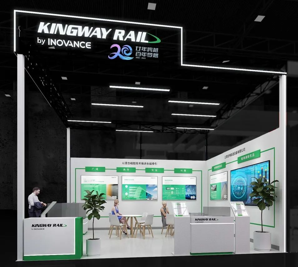
Metro permanent magnet direct drive traction motor

The number of poles of this permanent magnet synchronous direct drive motor is 12. Due to the use of the new silicon carbide technology, the motor achieves natural cooling. The motor is designed for subway vehicles and meets the requirements of IEC 60349-4. It adopts the shaft-holding installation method and is directly installed on the axle to drive an axle on the bogie.

Main features and advantages:

■ High-voltage silicon carbide (SiC) devices are used to replace traditional IGBTs, which realizes the miniaturization, modularization and integration of the converter, and increases the switching frequency, reduces the output voltage harmonics, and reduces the loss of the motor;

■ Due to the use of direct-drive motors, gearboxes and couplings are eliminated, which improves the overall efficiency of the transmission system and the energy saving rate of the system;

■ Thanks to the advanced natural cooling design of the motor, the weight of the motor is less than that of the traditional asynchronous motor plus gearbox and coupling, making the energy saving effect of the whole vehicle more significant;

■ Due to the closed structure of the direct-drive motor, the motor is in a relatively low-speed operation state, and there is no gearbox and internal fan, the system noise is reduced by 20dB, which improves the comfort of passengers;

■ The closed structure direct-drive motor with natural cooling is used, which reduces the daily cleaning and gearbox oil change work, and reduces the daily maintenance workload.

Silicon carbide power module

This product is used in the permanent magnet direct drive motor traction system. It integrates a three-phase inverter bridge, drive circuit, high-voltage bus circuit and filter, etc., forming a fully functional three-phase inverter that can drive a motor to work.

Main features and advantages:

■ The module uses high-voltage silicon carbide (SiC) MOSFET devices to replace traditional IGBTs, realizing the miniaturization, modularization and integration of the converter.

■ Based on the excellent characteristics of SiC devices, the converter increases the switching frequency, reduces the output voltage harmonics, and reduces the loss of the motor, which helps to achieve low noise, light weight, high efficiency and easy maintenance of the motor.

Permanent magnet synchronous traction motor for trams

This traction motor is a permanent magnet synchronous, 44-pole, water-cooled closed motor that meets the requirements of IEC 60349-4 and is powered by a permanent magnet traction inverter. The motor directly drives the vehicle wheelset through a clutch to provide power for the vehicle.

Main features and advantages:

Energy-saving, high efficiency, low noise, easy maintenance

■ The overall efficiency of the transmission system has been improved, and the system energy-saving effect is significant. Each permanent magnet direct drive motor drives one wheel, so that the vehicle has a better low-floor layout and small curve passing performance;

■ The direct drive motor adopts a closed structure, the motor is in a relatively low-speed operation state, there is no gearbox, and water cooling is used, which improves passenger comfort and reduces daily maintenance workload.

High-frequency auxiliary converter

Main features and advantages:

■ Strong redundancy: Each auxiliary converter box is equipped with 2 independent auxiliary inverter units and chargers. The 2 chargers in each auxiliary converter box are also connected in parallel for output, which improves the redundancy of battery charging and simplifies the wiring of the whole vehicle;

■ Fast grid connection: The 4 auxiliary inverter units adopt non-communication fast grid-connected power supply technology. Regardless of whether there is network communication or not, the grid connection operation of the auxiliary inverter of the entire train can be completed within 2 seconds;

■ Lightweight: The high-frequency soft switching technology is adopted, and the size of the transformer is significantly reduced;

■ Safety: The AC output adopts a three-phase four-wire system, and the neutral line ungrounded solution (IT system) is recommended, and an insulation detection device is configured in the auxiliary converter;

■ Easy to maintain: The power unit is modularized and miniaturized;

■ Intelligence: Supports the health management function of core components;

■ Mature application: Since 2014, high-frequency auxiliary converters have been used in batches, with a total of more than 1,000 units.

Traction health management unit

This product uploads the intelligent monitoring and diagnostic data of the traction system to the on-board wireless communication equipment and the ground server through Ethernet for big data analysis, and displays the intelligent diagnosis results through various terminals such as web pages and mobile APPs to achieve fault pre-diagnosis and provide maintenance advice information.

Main features and advantages:

Intelligent, scalable, strong performance

■ Support remote program update, easy maintenance;

■ Realize the pre-diagnosis of traction system equipment and component failures, greatly reducing daily operation and maintenance costs.

On-board LINUX system controller

Applied to scenarios such as air conditioning controllers, energy consumption recorders, and on-board health management units.

Main features and advantages:

■ High performance: using a high-performance 4-core A7 chip, the main frequency can reach 1.2GHz, support up to 16G storage space, and use LINUX operating system;

■ Deep localization: core components are all domestic products with mature applications;

■ Rich interfaces: support real-time Ethernet TRDP, MVB, CAN, RS485 and other communication interfaces;

■ Flexible configuration: with a main board and 4 slave boards (DIO1, DIO2, AIO, expansion valve), different application scenarios can be flexibly combined. The DIO board is compatible with 110V/24V DC, and the DO interface can be configured as DI through software. Voltage and current analog sampling can be configured through jumpers;

■ Mature and reliable: adopt hardware solutions with mature application experience, and verify the reliability of the solutions through environmental experiments;

■ Compact integration: the maximum width is only 270mm, and the screen can be integrated (optional);

■ Powerful functions: support data recorder (black box), custom offline fault diagnosis and other functions;

■ Easy to develop and debug: use the same maintenance software DISMON as the traction system. It can realize real-time data display, curve printing, and FPGA software remote burning functions. Fault protection logic, IO interface, and data recorder sampling variables can be configured through excel tables.

Those who strive first are the strongest, and those who innovate are strong. At this exhibition, Huichuan Jingwei Rail will gather the cutting-edge technologies of permanent magnets in the field of urban rail and the innovation of smart urban rail technology, decode the innovative technologies of cross-border integration of hybrid reluctance motors for new energy vehicles, and promote permanent magnet traction with hybrid reluctance technology. There are more exciting things~

April 27-April 29

China Railway Qingdao World Expo City S4 Hall

Booth S4402

See you in Qingdao!
Related product recommendations:
MVME51005E-0163
MVME162-223
MVME162-512
MVME162-522A
MVME162-533A
MVME162PA-344
MVME162PA-344E
MVME167-33A
MVME167-33B
MVME172-533
MVME188A
MVME2100
MVME2434
MVME2401
MVME2400
MVME2431
MVME2432
MVME2434
MVME2604761
MVME300
MVME3100
MVME333-2
MVME335
MVME374
MVME374-1
MVME5100
MVME51005E
More……

Rockwell Automation and Cognite Join Forces to Accelerate the Digital Era

Rockwell Automation and Cognite, a global leader in industrial data software, have announced a strategic partnership to further unlock the value of manufacturing data and accelerate technology change in the industry. Through this partnership, Rockwell Automation’s FactoryTalk® next-generation edge connectivity products that connect to plant assets, operations management applications and industry-specific analytics will be combined with Cognite Data Fusion®, Cognite’s leading industrial data operations platform, to create an industrial data hub that can be extended enterprise-wide.

Rockwell Automation’s products have a large presence in industrial automation, creating and processing data on a global scale. The Rockwell Automation and Cognite partnership will bring to market a unique and unified edge-to-cloud industrial data hub that makes sense of operational, engineering, enterprise and visualization data for manufacturing across industries.

The product transforms raw data into high-impact applications for real-time decision making and workflow improvements to ensure safe, efficient and sustainable operations. Following Cognite’s success in the energy industry, this collaboration will further enhance the edge-to-enterprise capabilities of Sensia, a joint venture between Rockwell Automation and Schlumberger.

“Manufacturers of all sizes are trying to access and derive value from data,” said Brian Shepherd, senior vice president of software and control at Rockwell Automation. “A unified information hub can provide a single source of data for all manufacturing data without having to invest heavily in costly proprietary platforms. The larger the enterprise, the more difficult it is to aggregate data from many different sources, let alone gain practical analytical insights from it in an affordable way. Our strong alliance with Cognite will directly address these problems.”

“We are very pleased to work with Rockwell Automation to further expand FactoryTalk products and enrich the data that is critical to its applications.” Girish Rishi, CEO of Cognite, said, “Cognite’s mission is to promote the development, operation and scale of industrial hybrid artificial intelligence solutions, which is also reflected in this cooperation. We look forward to working with Rockwell Automation to accelerate the pace of applied analysis and digital applications in the industrial field.”

Xiao Luo has something to say

As one of the global leaders in automation, informationization and digital transformation, Rockwell Automation has advanced technology and rich industry experience. It joins forces with partners to empower corporate innovation and provide unlimited help for digital transformation!
Related product recommendations:
ABB PM861AK02, 3BSE018160R1
ABB PM866K02 3BSE050199R1
ABB PM864A 3BSE018162R1
ABB PM862K01 – 3BSE076940R1
ABB PM866K01-EA 3BSE050198R2
ABB PM867K01
ABB PM864AK01
ABB PM861AK02 3BSE018160R1
ABB 3BSE050201R1 PM866-2
ABB 3BDH000503R1 PM803F
ABB PM861AK01 3BSE018157R1
ABB PM860AK01 3BSE066495R1
ABB PM866-2 3BSE050201R1
PPD513AOC-100440  3BHE039724R0C3D
PPD517A3011  3BHE041576R3011
PPD517  3BHE041576R3011
PPD512A10-454000  3BHE040375R103E
3BHE057901R0101  PCD235
PCD235C101 3BHE057901R0101
GFD563A102 3BHE046836R0102
GFD563A101 3BHE046836R0101
GF D563  3BHE046836R010
GFD563A102  3BHE046836R0102
ABB PM864AK01 3BSE018161R1
ABB PM866
ABB PP D113 PPD113 3BHE023784R2630 B01-26-111000
ABB PPD113 3BHE023584R2634
ABB 3BHE041576R3011 – PPD517 A3011
ABB PPD113 B01-26-111000 3BHE023784R2630
Honeywell TC-PPD011 51309241-125
ABB PPD113B01
ABB PPD113 3BHE023584R2634
ABB PPD104 3BHE017400R0101
ABB 3HAC026317-001
ABB 3BHE021887R0101 UB C717
GE IS2020JPDBG01
ABB AC800F PM 803F
ABB 3BHE024820R0101 PP D234 A101
More……

ABB e-Mobility and YKC Cloud Fast Charging jointly build a charging station on Shanghai Huqingping Highway to create a new smart charging ecosystem

ABB Electric Transportation provided 20 ABB Terra CA 182 series DC charging solutions for the Shanghai Huqingping Highway Charging Station, bringing car owners a more convenient, fast and efficient charging experience.

ABB Electric Transportation and YKC Cloud Fast Charging jointly completed the construction, installation and maintenance of the station.

ABB Electric Transportation invested in YKC Cloud Fast Charging Pre-C round in 2022, laying the foundation for jointly building a charging network.

Driven by policies and markets such as carbon neutrality and new infrastructure, the transportation industry, as one of the main sources of carbon emissions, is actively transforming towards a green and intelligent direction. As the process of automobile electrification continues to accelerate, the corresponding supporting charging infrastructure has also ushered in a new round of development peak.

Recently, ABB e-Mobility and YKC Cloud Fast Charge established the first high-power DC charging station in Shanghai, the YKC Cloud Fast Charge Shanghai-Qingping Highway Charging Station. This is another milestone cooperation between the two parties since ABB e-Mobility completed its investment in YKC Cloud Fast Charge Pre-C in 2022. The two parties will take this opportunity to combine their advantageous resources to strengthen cooperation and communication, jointly promote the construction of charging infrastructure, optimize the industrial layout, and continuously empower green and low-carbon travel and transportation carbon neutrality.

The YKC Cloud Fast Charge Shanghai-Qingping Highway Charging Station is located on Shanghai-Qingping Highway, backed by Hongqiao Airport. ABB e-Mobility provides 20 Terra CA 182 series DC charging solutions for the station, which can meet the charging needs of different types of electric vehicles such as taxis/online car-hailing, logistics vehicles, and buses, and provide car owners with safe, reliable, intelligent and convenient charging services. The Terra CA 182 series is a new DC charging system solution released by ABB Electric Transportation in 2022. It has a rated power of 180kW and an ultra-wide voltage of 200V-1000V. It has strong adaptability and can cover about 99% of the vehicle models on the market. The charging success rate can reach more than 95%, greatly improving the asset operation efficiency of the station. At the same time, the Terra CA 182 series also has orderly charging management on the local and platform side, which can not only adjust the power load, but also achieve friendly complementarity with the local power grid. The charging pile has its own remote monitoring and diagnosis function, which can quickly locate on-site needs, can be remotely upgraded through the platform, reduce on-site operation and maintenance time, and thus improve the operation efficiency of the station.

Providing the public with a better charging environment, accelerating the layout of energy replenishment, and promoting the high-quality development of the new energy industry are the common cooperation visions of ABB Electric Transportation and YKC Cloud Fast Charging. Cao Yang, head of ABB e-Mobility in China, said, “As the penetration rate of electric vehicles gradually increases, the demand for charging has increased on a large scale, and people have higher requirements for the charging speed, charging stability and compatibility of charging piles. ABB e-Mobility and YKC Cloud Fast Charge have strategically joined hands to build the Cloud Fast Charge Shanghai Qingping Charging Station, which not only brings users a more efficient, convenient and fast charging experience, but also takes this as a starting point to further promote the construction of supercharging infrastructure, create a more intelligent charging new ecology, and lead green and low-carbon travel.”

Frank N. Chen, President and CTO of YKC Cloud Fast Charge, said: “As a new energy vehicle charging service and energy management solution provider with the second largest public charging service network in my country, YKC Cloud Fast Charge also maintains a leading position in the number of DC fast charging terminals, ranking second in the country 1 . This time, we joined hands with ABB e-Mobility to promote the landing of the YKC Cloud Fast Charging Shanghai-Qingping Highway Charging Station, which not only ushered in the expansion of the fast charging energy supply network, but also broadened the application possibilities of YKC Cloud Fast Charging in the field of comprehensive energy management. We have double-line improved the safety and economic benefits of the station through measures such as software and hardware power adjustment and platform precision management, and met the needs of users for efficient, stable and safe energy replenishment. In the future, we will continue to uphold the concept of “making charging better and energy more efficient”, and work with ABB e-Mobility to promote the construction of charging infrastructure and strive to become the best travel energy replenishment partner for every new energy vehicle owner. ”

ABB e-Mobility is a global market leader in creating a zero-emission future, committed to providing smart, reliable and zero-emission electric vehicle charging solutions. ABB e-Mobility entered the electric vehicle charging market in 2010 and has now delivered more than 1 million charging piles in 85 countries and regions, including more than 50,000 DC charging piles and more than 1 million AC charging piles, as well as charging piles sold through Chargedot.
Related product recommendations:
ABB PM861K01 3BSE018105R1
ABB VPM810
ABB PM857K01
ABB PM858-C 3BSE093350R1
ABB PM810V2 3BSE013220R1
ABB PM866K01 3BSE050198R1 
ABB PM857K02
ABB PM851AK01 3BSE066485R1
ABB VPM810
ABB PM865K01 3BSE031151R1
ABB PM863K02
ABB PM864AK01 3BSE018161R1
ABB PM861K01 3BSE018105R1
ABB PM802F
ABB PM861AK01 3BSE018157R1
ABB PPD114B 3BHE020570R
Honeywell TK-PPD011
PCD235C101 3BHE057901R0101
GFD563A102 3BHE046836R0102
GFD563A101 3BHE046836R0101
GF D563  3BHE046836R010
GFD563A102  3BHE046836R0102
ABB 3BHE041576R3011 PPD517 A3011
ABB 3BHE020455R0001 PPD103 B01
ABB 3BHE020455R0001 – PPD103 B01
ABB PPD512 A10-15000
ABB PPD113B01  3BHE023784R1010
GE IS220PPDAH1A
Honeywell TK-PPD011
More……

Bently Nevada 3500/01-01 - Advanced Industrial Automation Solution

3500/22M TRANSIENT DATA INTERFACE

Description

The 3500/22M Transient Data Interface (TDI) is the interface between the 3500 monitoring system and compatible software (System 1 Condition Monitoring and Diagnostic software and 3500 System Configuration software). The TDI combines the function of a 3500/20 Rack Interface Module (RIM) with the data collection capability of a communication processor such as TDXnet.

The TDI resides in the slot adjacent to the power supplies of a 3500 rack. It interfaces with M series monitors (3500/40M, 3500/42M, etc.) to continuously collect steady state and transient dynamic (waveform) data and pass this data through an Ethernet link to the host software. Refer to the Compatibility section at the end of this document for more information.

Static data capture capability is standard with the TDI. However, using an optional Channel Enabling Disk will allow the TDI to capture dynamic and high-resolution transient data as well. The TDI incorporates the communication processor function within the 3500 rack.

Although the TDI provides certain functions common to the entire rack, it is not part of the critical monitoring path and has no effect on the proper, normal operation of the overall monitor system for automatic machinery protection. Every 3500 rack requires one TDI or RIM, which always occupies Slot 1 (next to the power supplies).

I/O Module Signal Common Terminal

Both versions of the TDI I/O Module now include a 2-pin connector for connecting Signal Common to a single point Instrument Ground for the rack. When this is done, the selector switch on the side of the Power Input Module (PIM) must be slid in the direction of the arrow marked “HP” to isolate Signal Common from chassis (safety) ground.

3500 22M Dynamic Data Enabling Disk

This disk enables the number of channels of dynamic data (i.e., the ability to collect waveforms) that the TDI will support. There are two levels of dynamic data. Steady-State points are channels that collect waveform data due either to a software command or to an alarm event, and therefore support current values, scheduled waveform capture, and alarm data capture. Transient points provide all the function of a Steady-State point with the additional capability of waveform collection due to parameter variations such as machine speed.
Related product recommendations:
Bently Nevada 3500
Bently Nevada 3500/01-01
Dell Precision T3500
Bently Nevada 3500/64M
Bently Nevada 3500/25
Bently Nevada 3500/22-01-01-CN
Bently Nevada 3500 Series 93-07-01-02-00
GE/Bently Nevada 3500/15
Bently Nevada 3500/54M
Bently Nevada 3500/25 149369-01
Bently Nevada PLC 3500/05-01-01-CN-00-01
BIOQUELL TD060-3500
BENTLY 3500/22M 146031-01
BENTLY 3500/50 133388-02
Bently Nevada 3500/22M 138607-01
Bently Nevada 3500/50-04-01
PPD517A3011 3BHE041576R3011
Bently Nevada 135489-01
GE/Bently Nevada 1900/65A
AB Industries 2711E-K10C15
AB 81000-199-51-R
GE PC6790896
ABB YPM102A YT204001-AA
more……

EMERSON A6500-RC High Performance Universal Measurement Card

A6500-RC-SYSTEM-RELAY-CARD-EN-9881078

Application

The A6500-RC Relay Card is a component of the AMS 6500 ATG machine protection system. It is a freely programmable microprocessor-controlled module that can be used to do logical combination of binary signals within a AMS 6500 ATG system. When connected to an A6500-xR System Rack, the measurement cards provide and connect their logical outputs (COK, Alert, and Danger) automatically to the A6500-RC inputs through the backplane of the System Rack.

The A6500-RC captures the signals to logically combine them and provide the results through relay outputs. The A6500-RC is intended to be used in an A6500-xR System Rack (A6500-SR, A6500-RR, or A6500-FR) which is equipped with a separate slot for the A6500- RC.

The A6500-RC Relay Card is equipped with 66 digital, galvanically separated input channels (24 V logic), 16 output relays, one green system status LED and 16 yellow relay status LEDs on the monitor front to indicate the output relay statuses. All 66 input channels can be used separately and can thus be combined with each other individually. The 16 output relay channels are designed as single-pole switchover contacts (SPDT).

Connection of external digital signals is possible if using an A6500-RR system rack or an A6500-FR system rack. The A6500-RC card is not mandatory for the operation of an AMS 6500 ATG.

In conjunction with the A6500-CC Com Card status data of the A6500-RC can be provided through Modbus RTU, Modbus TCP/IP and OPC UA. As the Relay Card is designed for use with A6500-xR System Racks , generally a Com Card is required for configuration purposes.

Design

The A6500-RC Relay Card is designed as a double-standard Euro card (100 mm x 160 mm). The mechanical dimensions of the card match the dimensions of corresponding A6500-xR System Racks exactly. The front plate dimension of the A6500-RC is 3RU height and 10HP width. As the A6500-RC is manufactured in sandwich board design, the main board is equipped with a 96-pole terminal connector and the relay board is equipped with a 48- pole terminal connector (IEC 60603-2, F 48 M) to connect the respective backplane slot. Figure 3-1 shows the side view of the Relay Card.

Installation

For installation and mounting of the A6500-RC into an A6500-xR System Rack the relay output terminals and wiring are described in the operation manual of the A6500-xR System Racks. The Relay Card can be only installed in the double slot 12 (12.1 and 12.2) of the A6500-SR System Rack or in the double slots 10 (10.1 and 10.2) and 11 (11.1 and 11.2) of the A6500-RR System Rack.

General configuration procedure

The configuration can be performed offline, that means without connection to the card or online with a connection to the card. In any case, the configuration has to be loaded into the card. The A6500-CC Com Card is required for the configuration procedure. See Com Card operating manual for details.

Requirements:

A6500-CC Com Card (only online configuration)

A6500-RC Relay Card installed in an A6500-xR System Rack (only online configuration)

Power supply (only online configuration)

USB cable with Type-A and Type-B plug or Ethernet cable (only online configuration)

AMS Machine Studio (configuration software)

PC or laptop with Microsoft Windows 10

These buttons are available when a Module page is selected from the list of configuration pages. Use the Editor and Online buttons to toggle between the editor view and the online view. The button of the selected view is highlighted.

Editor In the editor view, configure logics as described in Module 1 to Module 32

Online In the online view, check the configured logics already stored in the A6500-RC. The online view requires an online connection to the A6500-RC card and no changes in any Module. To ensure that the shown configuration is the configuration stored in the A6500-RC card click Reload (see Reload).

Note

To check a changed Module, send the configuration with the changes to the A6500-RC before.

It is not possible to make any changes to the configuration in the online view except to Basic. Switch back to the editor view to change logics.

Simulate input signals to see if the created logic reacts as expected. How to simulate input signals is described in Functional check.

Elements are colored based on their logic state:

Elements that are logic 1 are colored red

Elements that are logic 0 are colored blue.

Current timer values are colored green.

The logic state is also shown with 1 or 0 at the input and output of each element. See Figure 6-18.

The online view requires a stable connection between AMS Machine Studio and the A6500-RC card, otherwise the logic values cannot be displayed. A disturbed connection is indicated with the note shown in Figure 6-19.
Related product recommendations:
ALSTOM AB121
3BHE014023R0101 UFC789AE101
PPD513AOC-100440  3BHE039724R0C3D
6DS1916-8AA
KJ3102X1-BE1
IS200EMIOH1AFB
VE4017P0
51405098-100
TC-201-01-4M5
KJ3222X1-BA1
5301-MBP-DFCM
6ES7 953-8LG30
3BHT300054R3/A XI-11
TTM211 IP166 L54E60000311
IS200TVBAH2A
IC3600VMPA1E
Bently Nevada 3500/72M-03-01
1KGT030400R0001
Bently Nevada 74712-06-05-03-00
more……

Search for products

Back to Top
Product has been added to your cart