
Configuration
The user defines monitor operation and the Modbus Gateway register map by using software running on a laptop or PC to create a configuration file and download the file to the monitor through the built-in Ethernet connection. The 1900/65A permanently stores configuration information in non-volatile memory, and can upload this information to the PC for changes.
Display Module
The 1900/65A supports an optional display/keypad to view channel information or make minor configuration changes. This allows the 1900/65A to operate as a stand-alone package. If desired, the user can mount the display up to 75 metres (250 feet) from the Monitor Module.
Specifications Inputs
Transducer Inputs
Users can configure Channels 1 through 4 to accept input from acceleration, velocity or displacement transducers.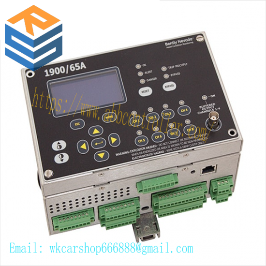
Transducer Channel Types
Channel Types define the functionality for processing that will be applied to an input signal and the kind of variables or measurement values that will be derived from this input. Channel Types also define the kind of sensor that must be used. Transducer Channel Types include:
Acceleration or Reciprocating
Acceleration
Velocity or Reciprocating Velocity
Radial Vibration (shaft vibration)
Thrust (shaft axial displacement)
Position
Speed
Acceleration and Reciprocating Acceleration Channel Types
The Acceleration Channel Type and Reciprocating Acceleration Channel Type support two- and three-wire acceleration sensors. The Reciprocating Acceleration channel type has timed OK channel defeat disabled.
Acceleration Variables and Reciprocating Acceleration Variables
Acceleration Variables and Reciprocating Acceleration Variables are filtered and processed measurements from raw transducer signals. The Acceleration Channel Type and Reciprocating Acceleration Channel Type continuously processes up to four variables per channel.
Velocity and Reciprocating Velocity Channel Type
The Velocity Channel Type and Reciprocating Velocity Channel Type support two-wire and three-wire piezovelocity sensors.
Velocity Variables and Reciprocating Velocity Variables
Velocity Variables and Reciprocating Velocity Variables are filtered and processed measurements from raw transducer signals. The Velocity Channel Type and Reciprocating Velocity Channel Type support up to four continuously calculated variables per channel.
Inhibit/Trip Multiply
Users can use software to configure the Inhibit/Trip Multiply input as either Inhibit or Trip Multiply
When configured for Trip Multiply shortcircuiting the Inhibit/Trip Multiply contact to RTN will increase Alert and Danger set points.
When configured for Inhibit the Inhibit input will inhibit (bypass or inactivate) Alert and Danger statuses. Short circuiting the INHIBIT contact to INHIBIT RTN will:
Set all Variable Danger Statuses to logic 0
Set all Variable Alert Statuses to logic 0
Set Bypass and Inhibit Statuses to logic 1
Reset
Use the Reset input to reset all latched alarms and latched relays. If the condition driving the status no longer exists, short-circuiting the RESET contact to RESET RTN will:
Reset all latched Alert statuses
Reset all latched Danger statuses
Reset all latched Not OK statuses
Reset all latched relays
Display Module
A single buffered output on the Display Module provides access to input Channels 1 through 4. The signal does not have gain, and is not scaled. This output is buffered to provide short circuit and EMI protection.
Monitor Module
Each input for channels 1 through 4 has a dedicated buffered output. The signal does not have gain, and is not scaled. Each output is buffered to provided short circuit and EMI protection.
The 1900/65A provides default configuration settings for Bently Nevada transducers. The user can configure the 1900/65A to accept other transducers.
This monitor is not certified for installation in Class 1 Div 1 locations, but it will support transducers installed in Div 1 locations via the use of galvanic isolators and barriers. If galvanic isolators are used, no change is necessary to the installation. A removable ground jumper allows the monitor to support zener barrier installations. Removing the jumper will disconnect circuit common from chassis at the monitor so that chassis can be connected at the barrier.
Related product recommendations:
ABB UFC721BE101 3BHE021889R0101
ABB GFD233A 3BHE022294R0101 3BHE020356R0101
ABB PU516 3BSE013064R1
ABB 3BSC950125R1
ABB XO08R2-A4.0
ABB 1SAP210600R0001
ABB 5STP06D2800
ABB ACSM1-04AS-046A-4
ABB 5SHX0660F0002
ABB ACS310-03E-13A8-4
ABB MDO32BNS MODULE
ABB PP845A – 3BSE042235R2
ABB SYN5200a-Z, V217 3BHB006713R02
ABB PFCL201CE-20.0KN 3BSE027062R20
ABB PFEA112-65 3BSE030369R65
ABB 3BHE005656R0001
More…


Leave a comment
Your email address will not be published. Required fields are marked *